Tag Archives: Tagebuch

A new model is made – final

This is the last part of the series, final.

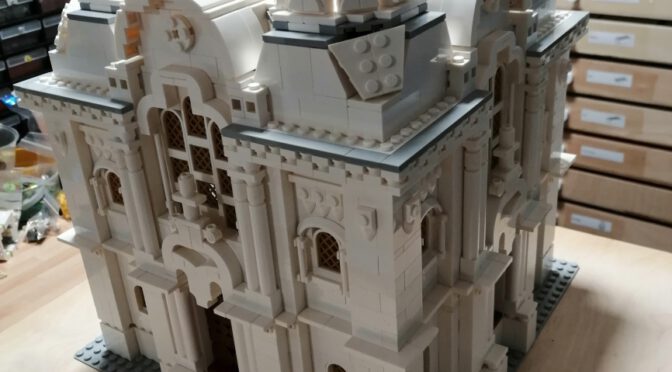
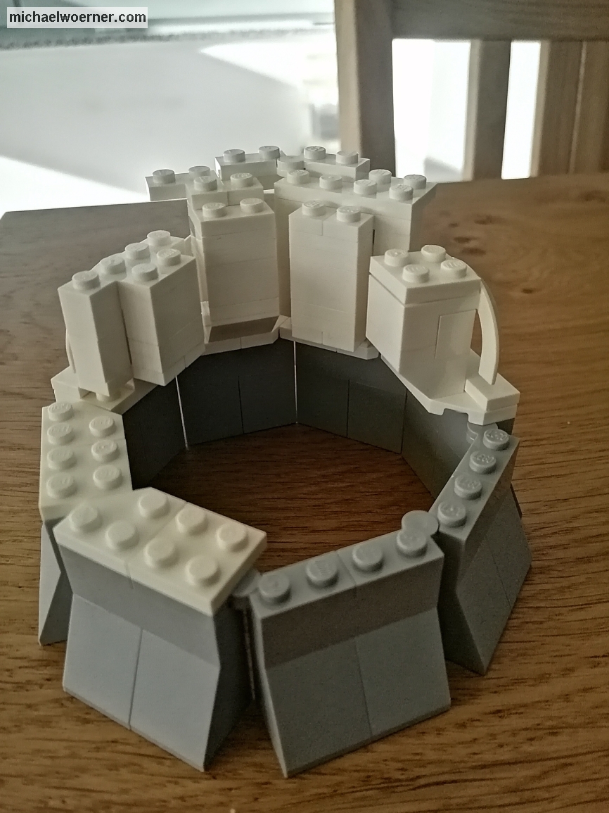
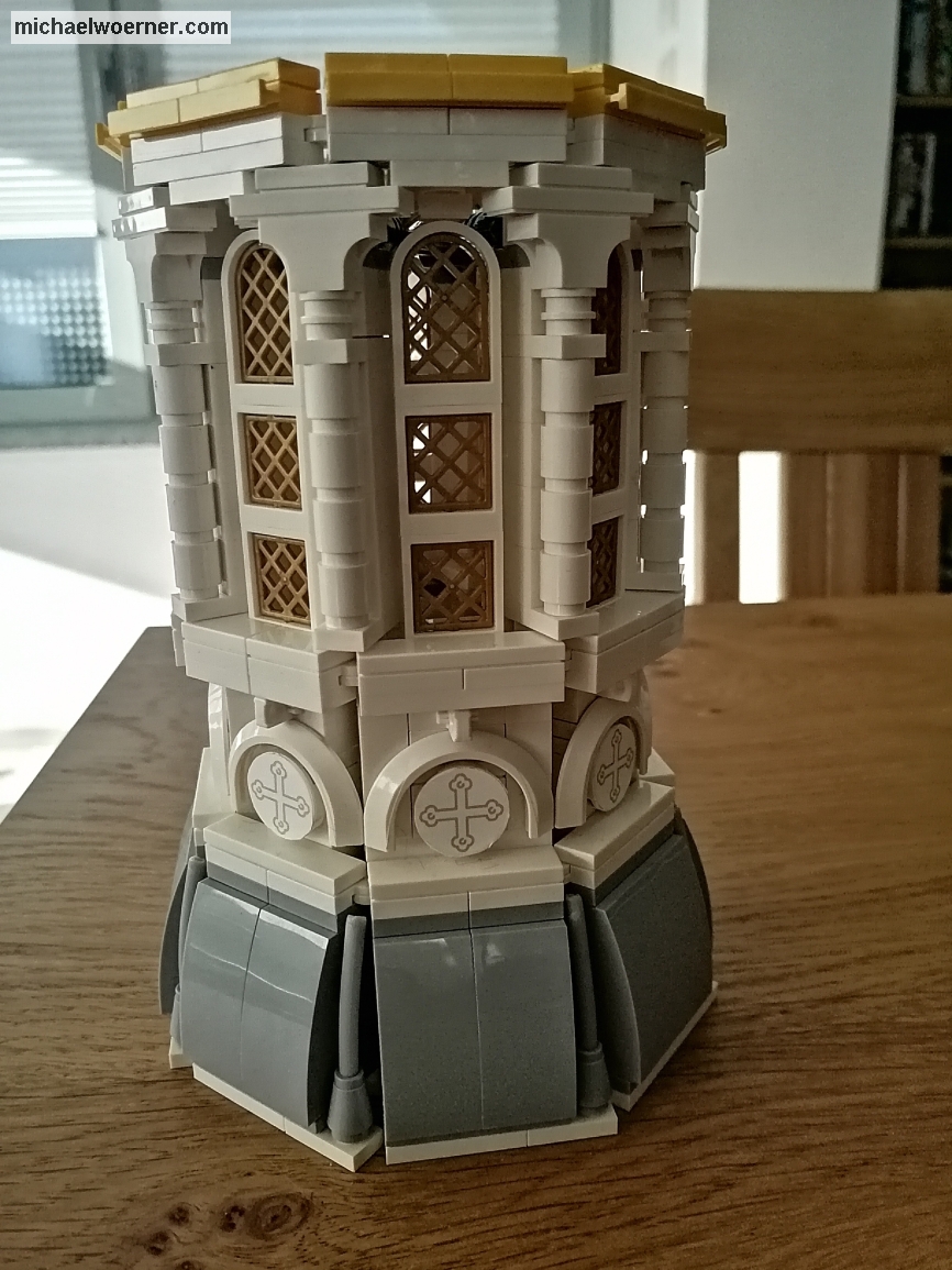
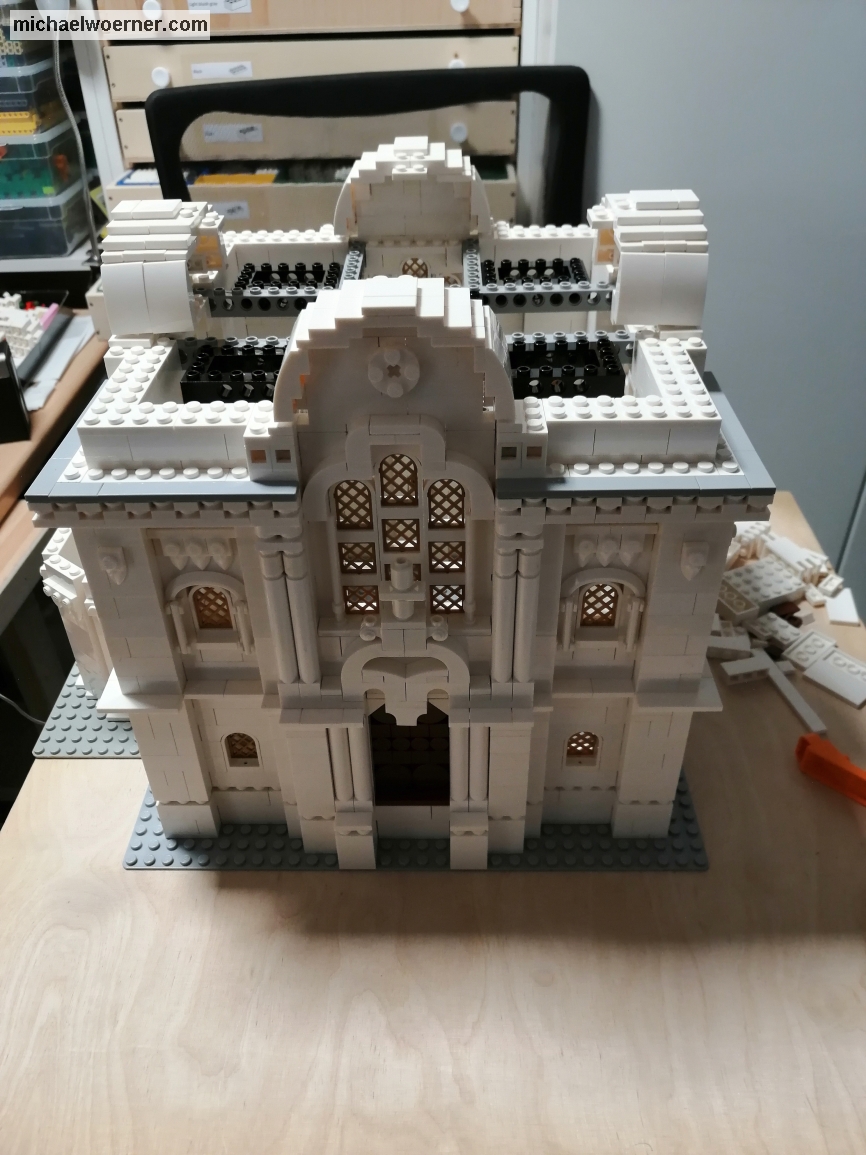
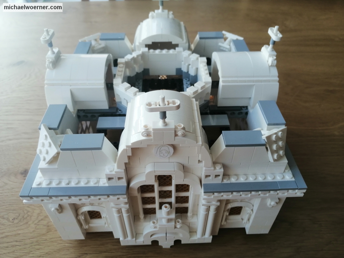
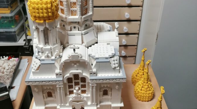
If you still haven’t guessed, the model represents the Greek Orthodox chapel on the Neroberg at the northern end of Wiesbaden.

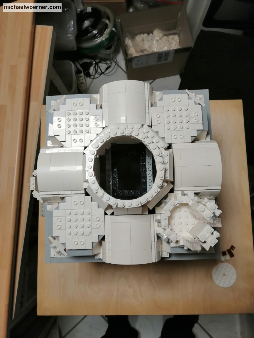
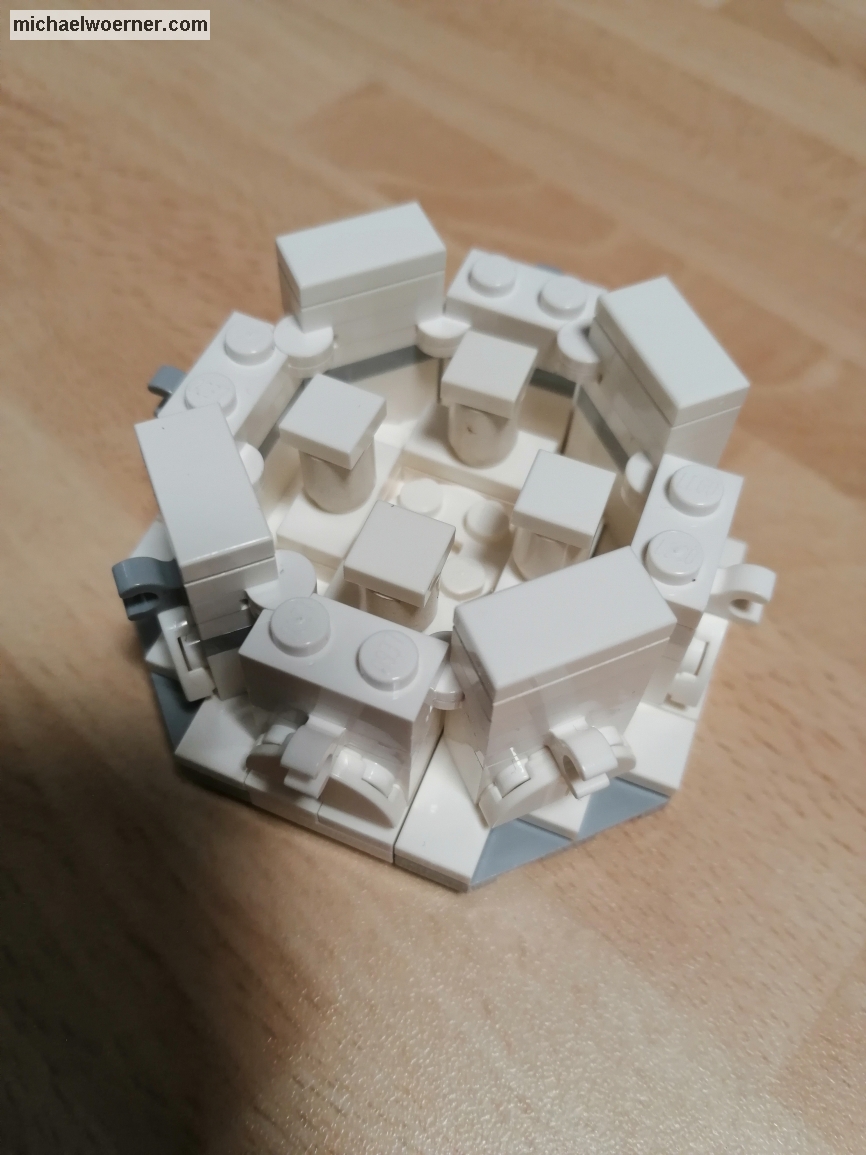
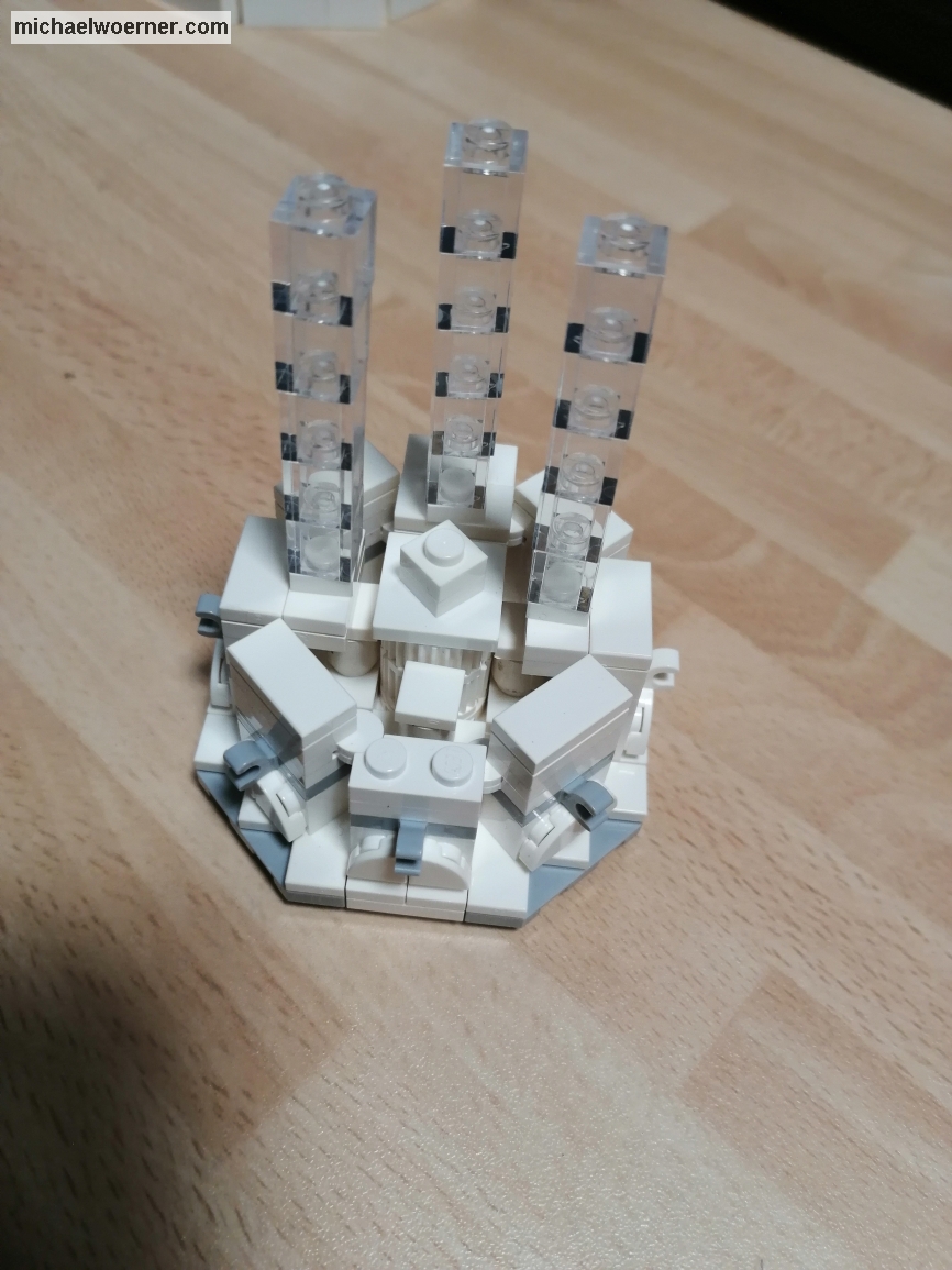
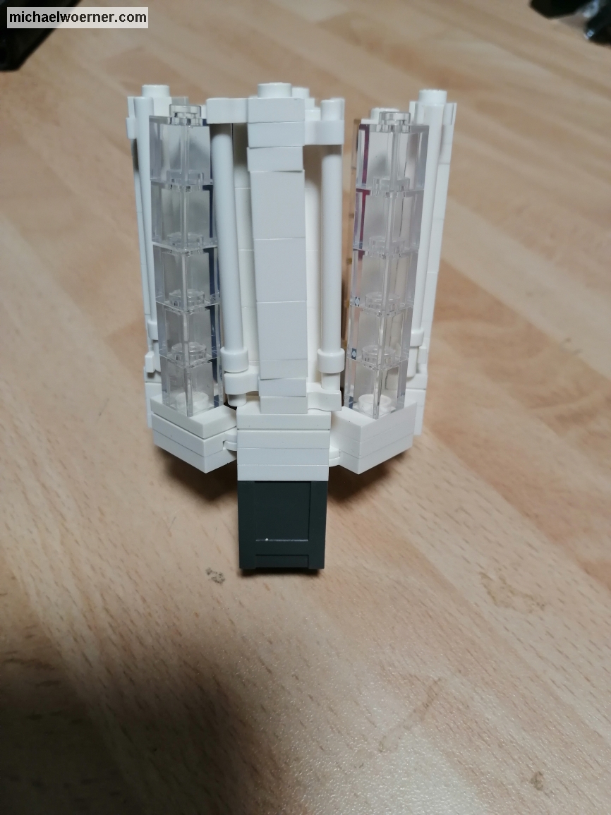
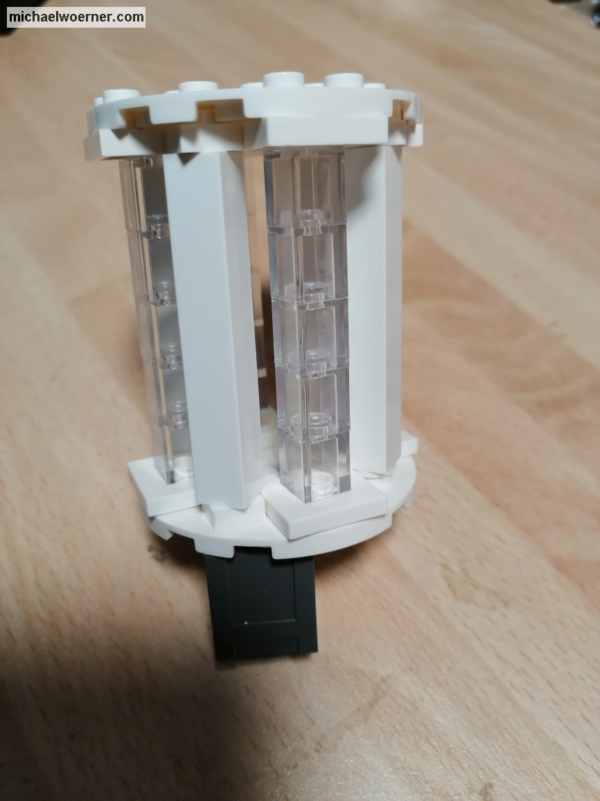
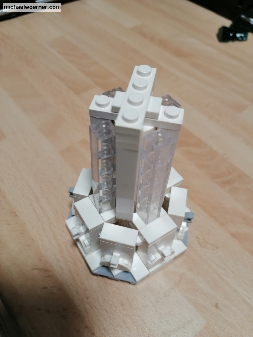
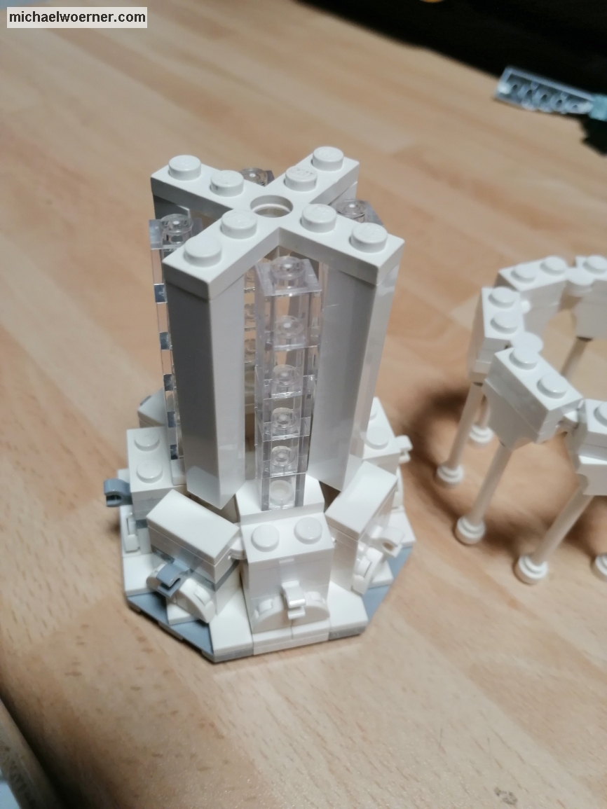
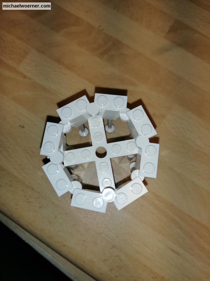
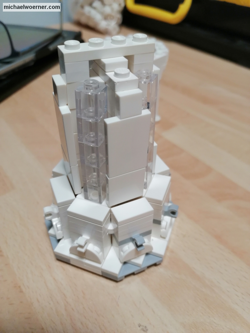
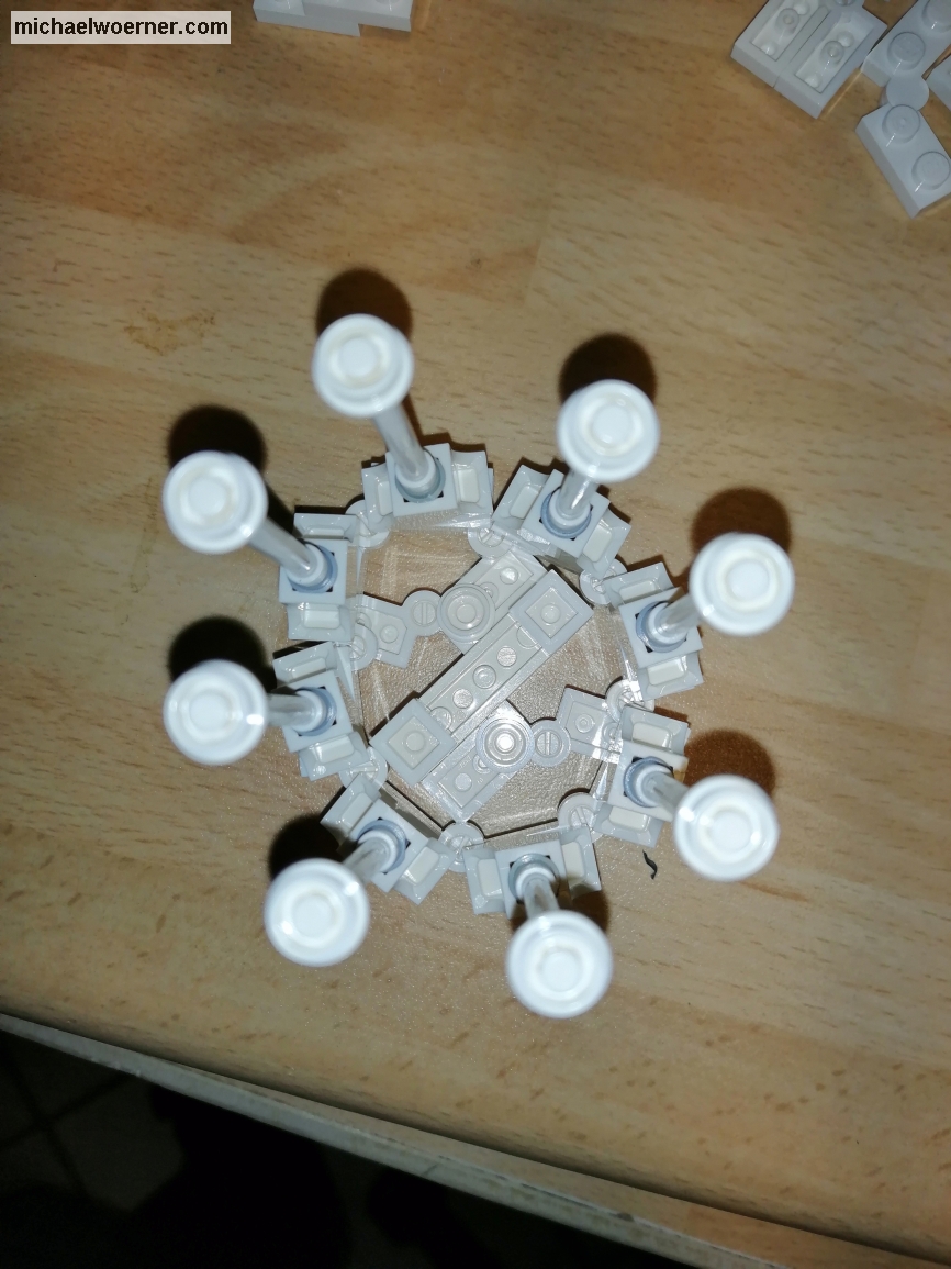
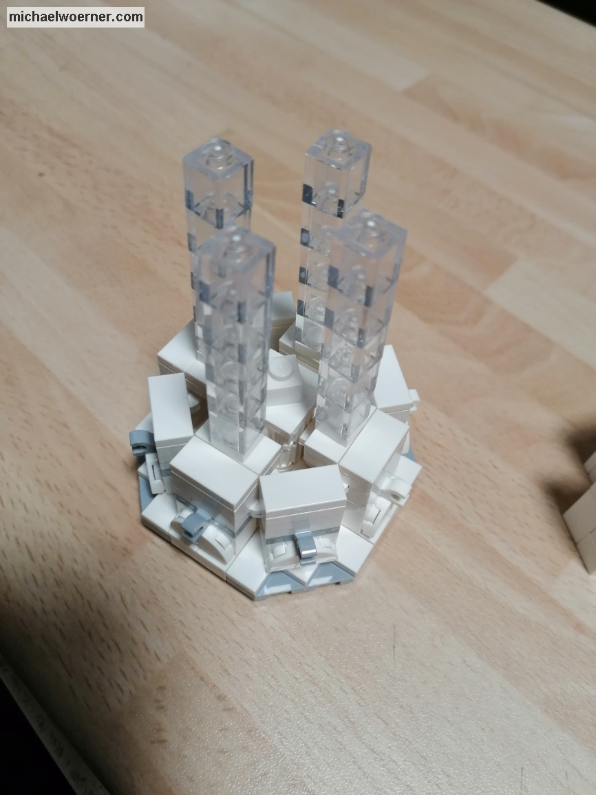
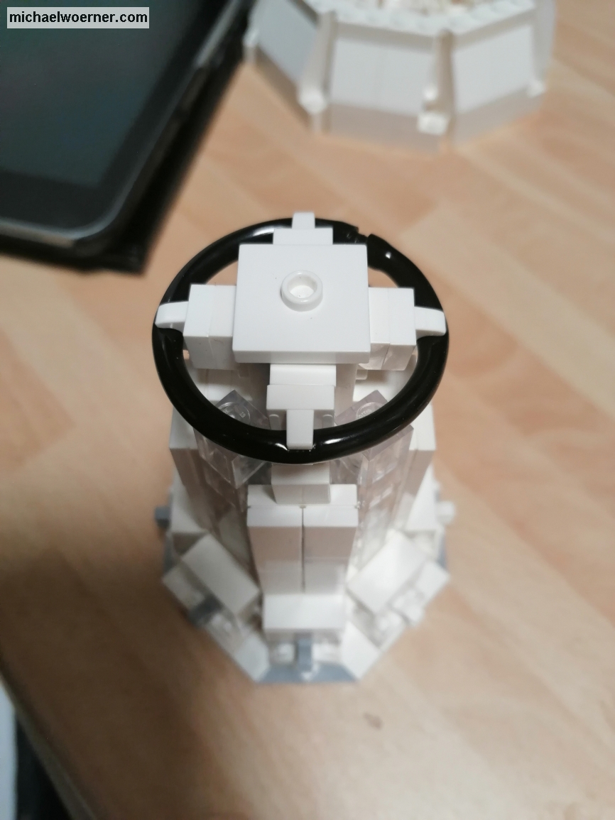
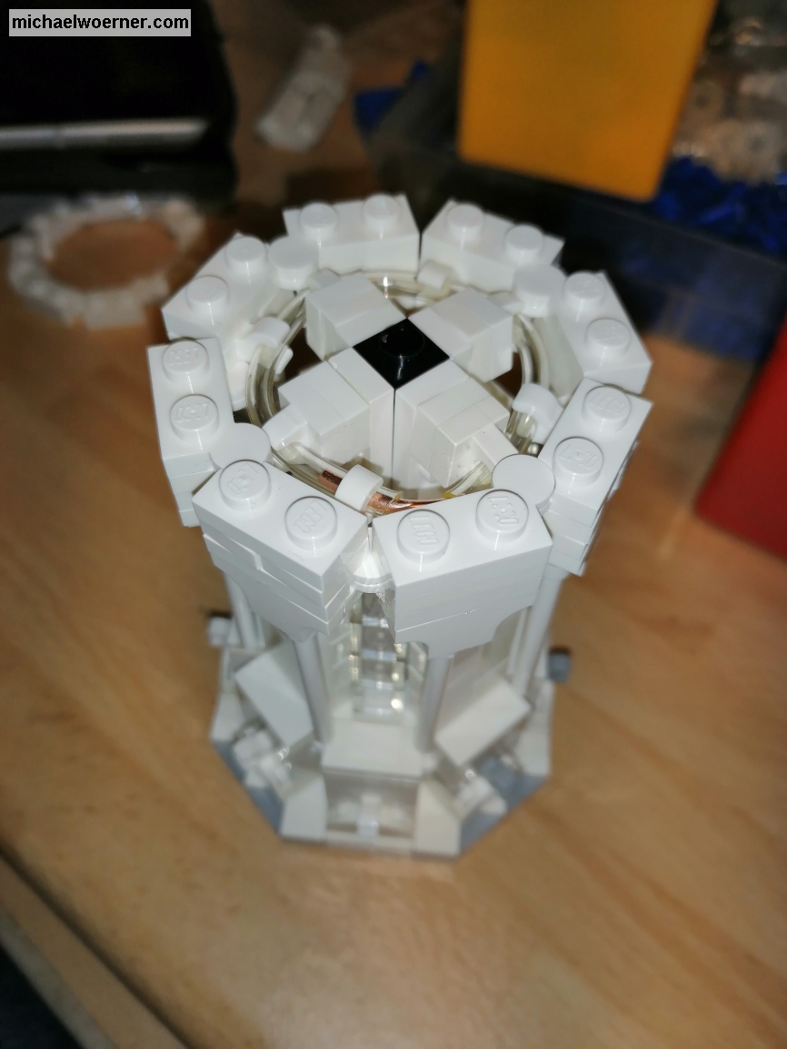
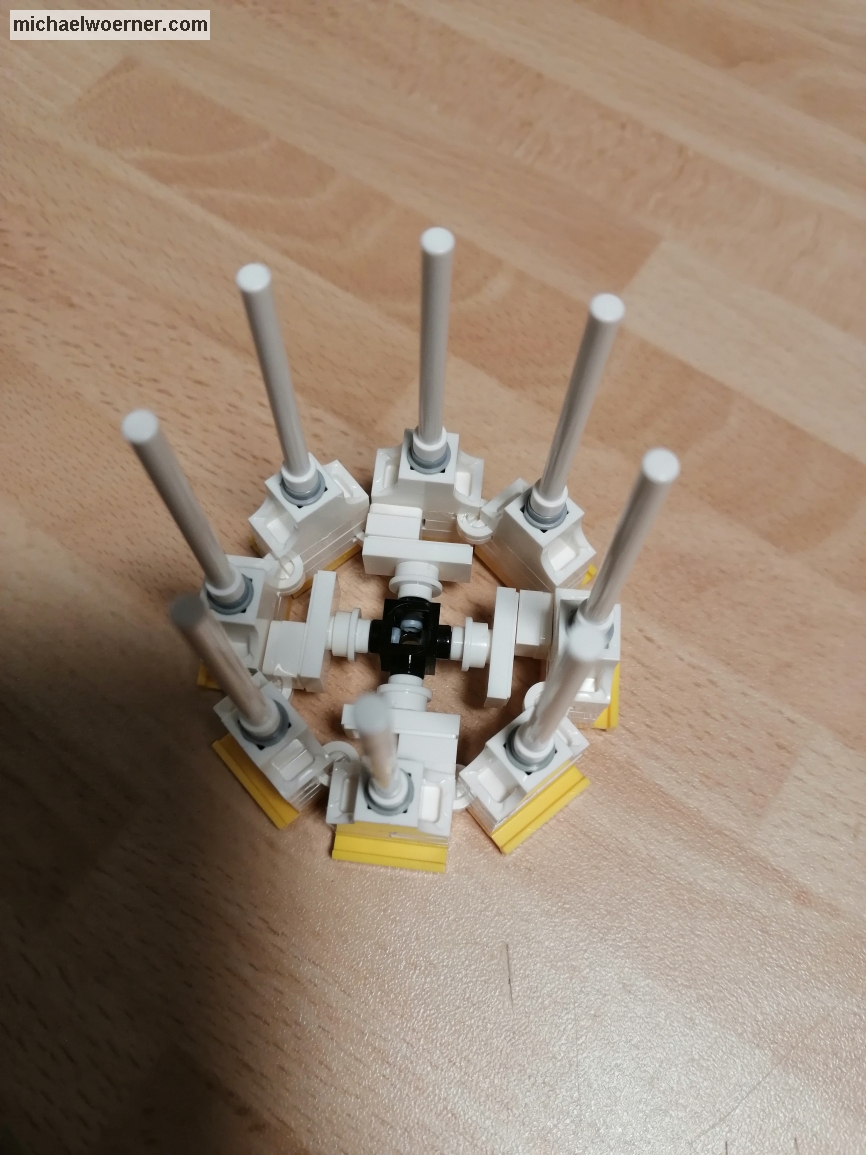
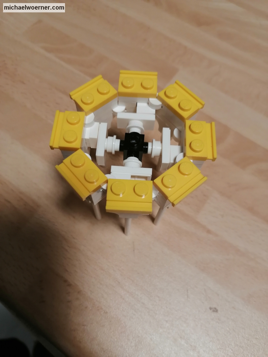
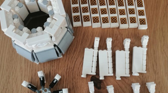
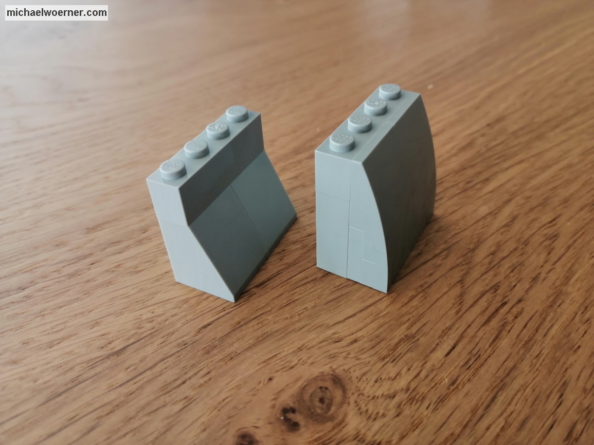
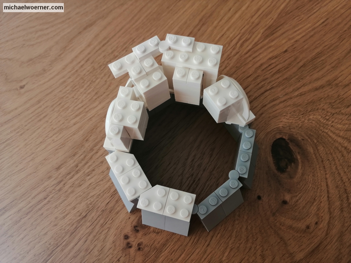
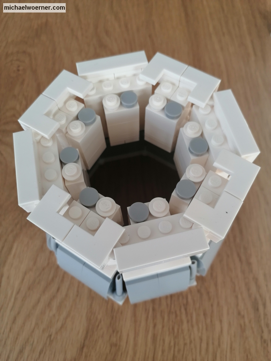
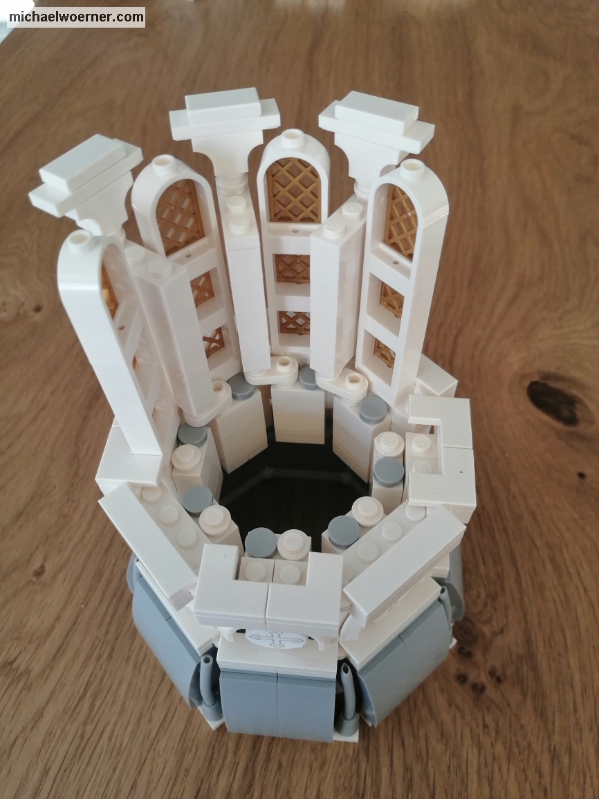
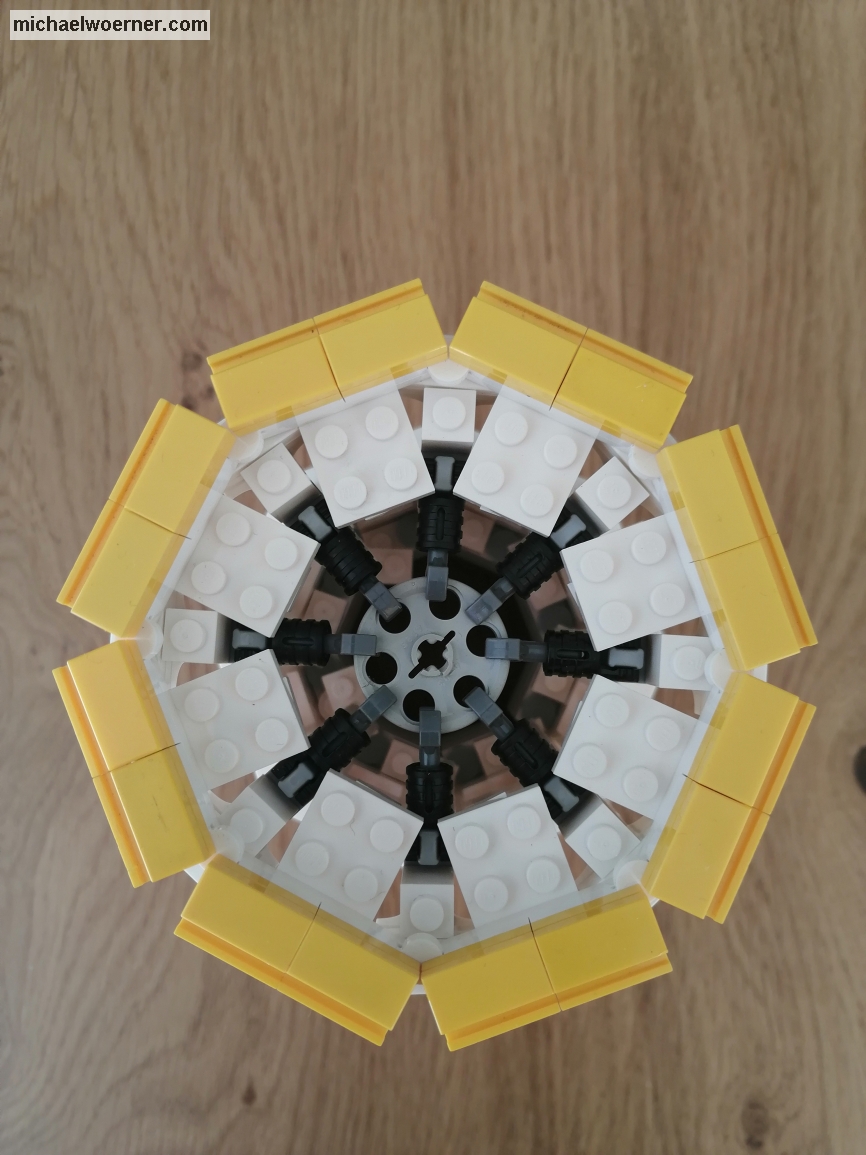
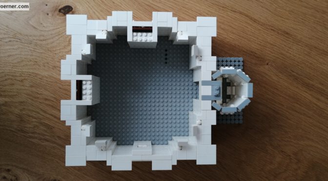
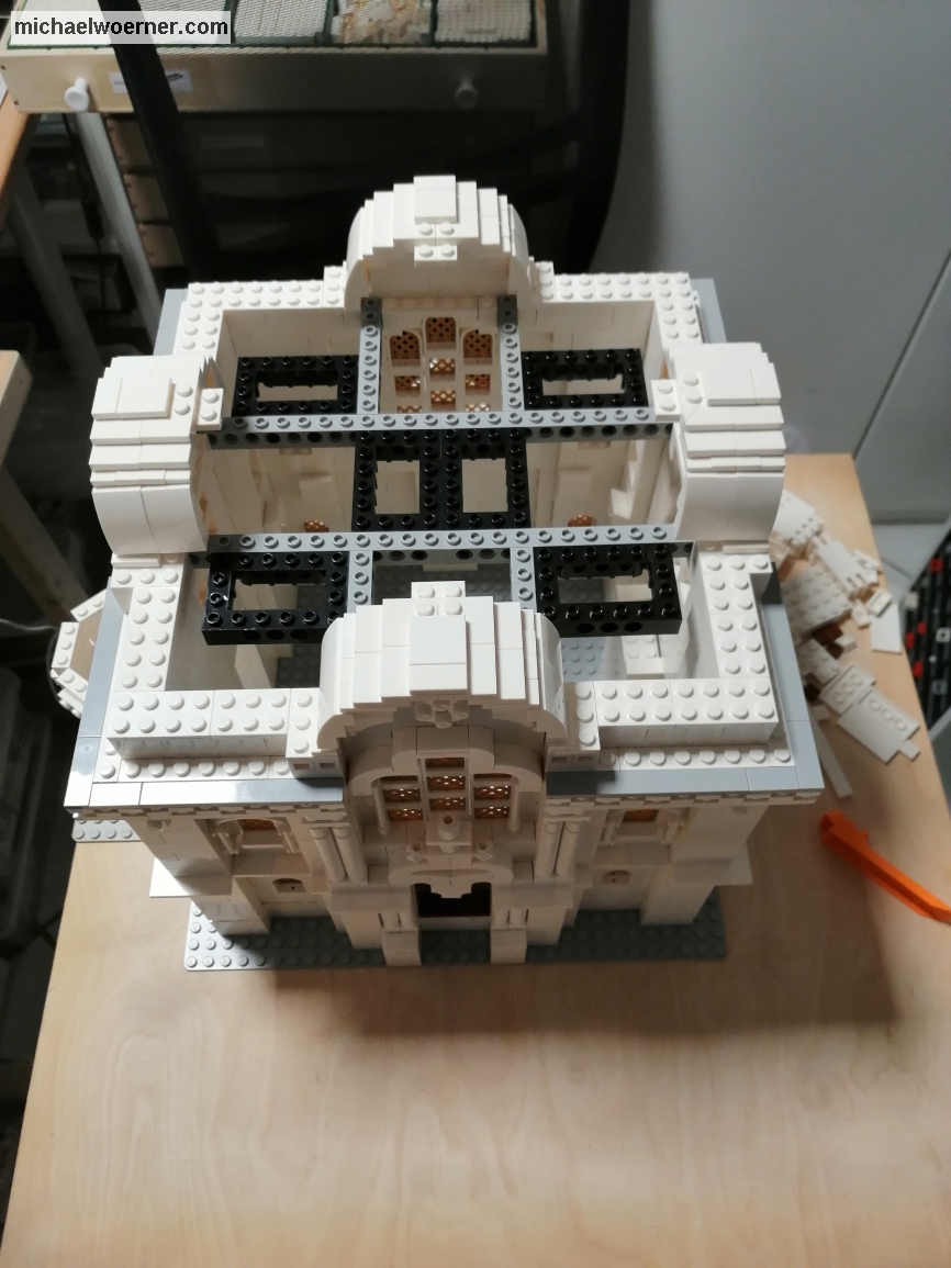
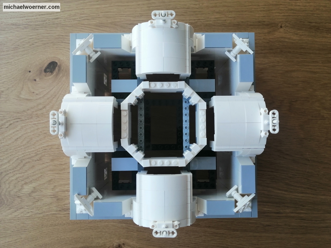
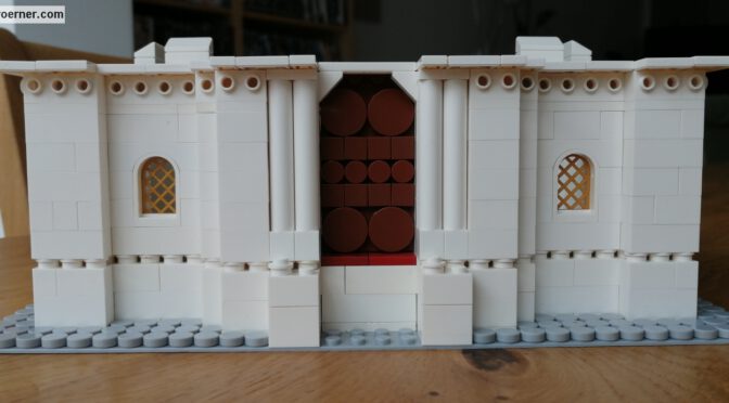
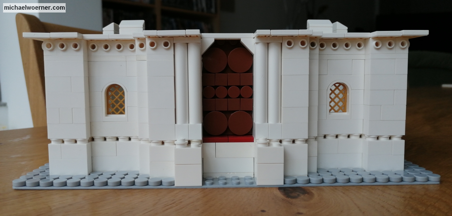
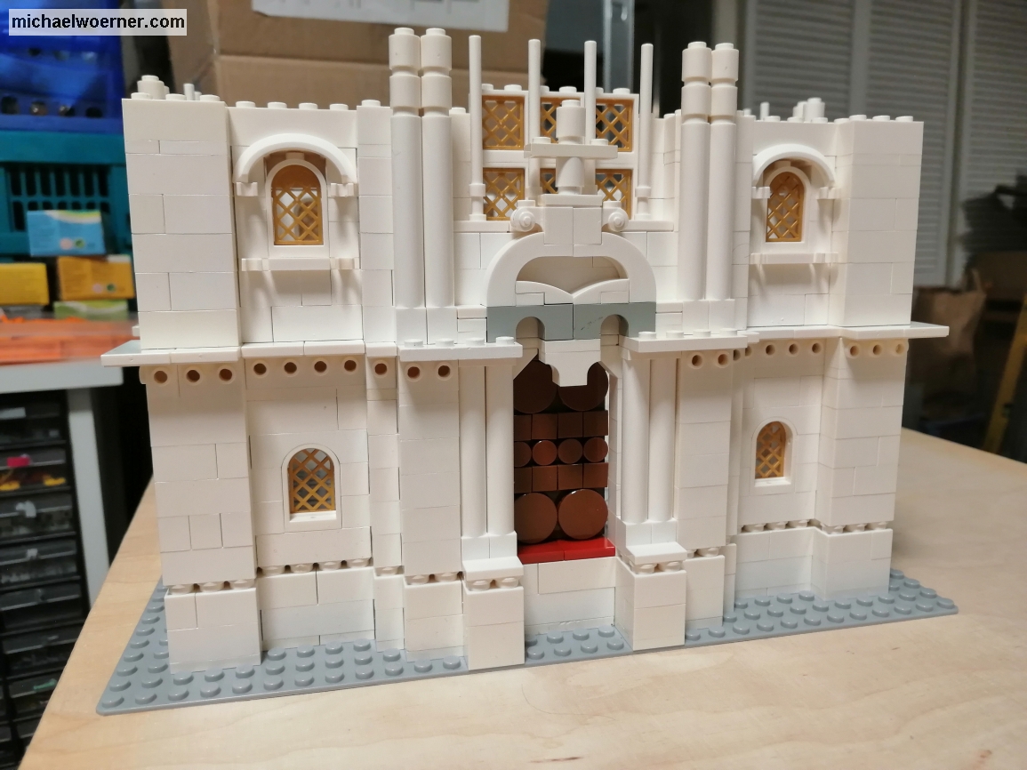
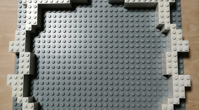
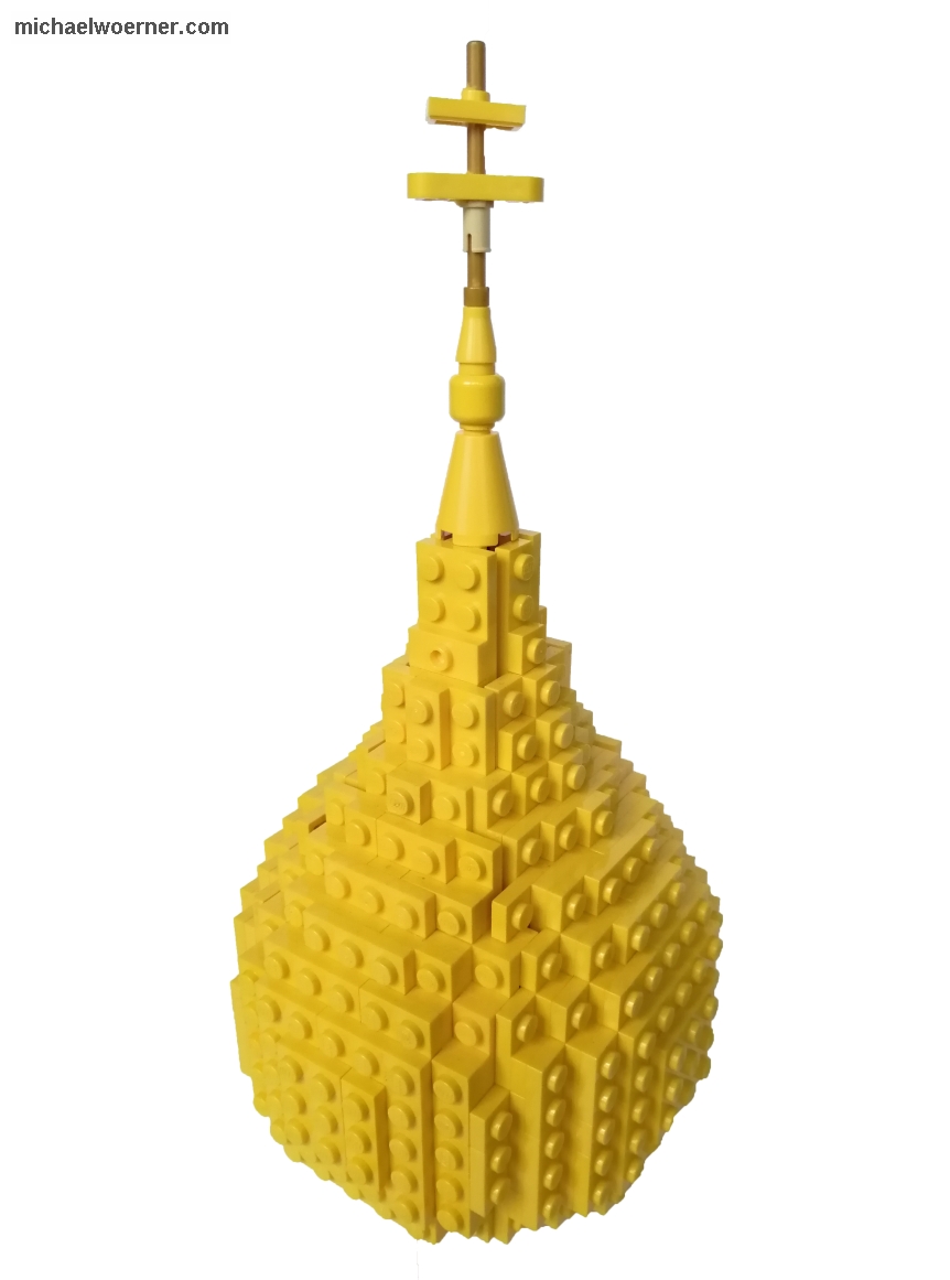
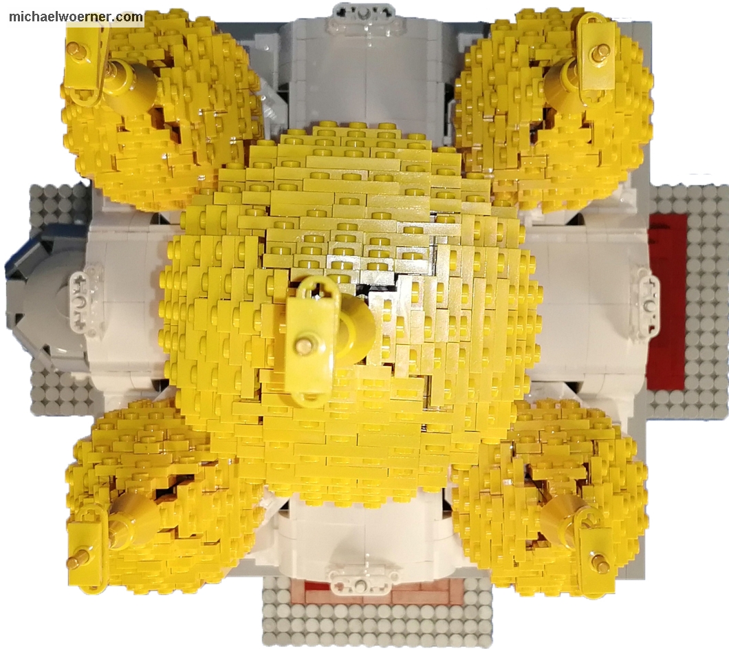
After building the walls at the beginning and then the towers, it is now the turn of the towers at the end. There are many ways to build such domes. I chose the SNOT technique (Studs not on top). Here, 6 identical elements are assembled to a cube using stones with pins on the side. However, the parts are not flat but arched, so that a ball is formed. I have incorporated and modified this approach. I do not need a floor and the lid is not needed by pulling up the side walls to a point. 5 domes are needed. Four of them, for the corner towers, have an inside diameter of 5 pins.


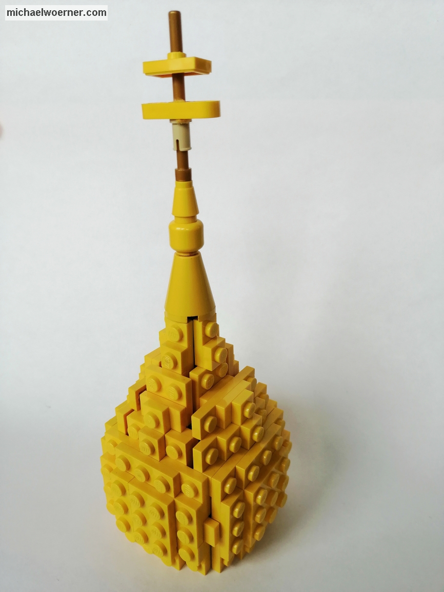
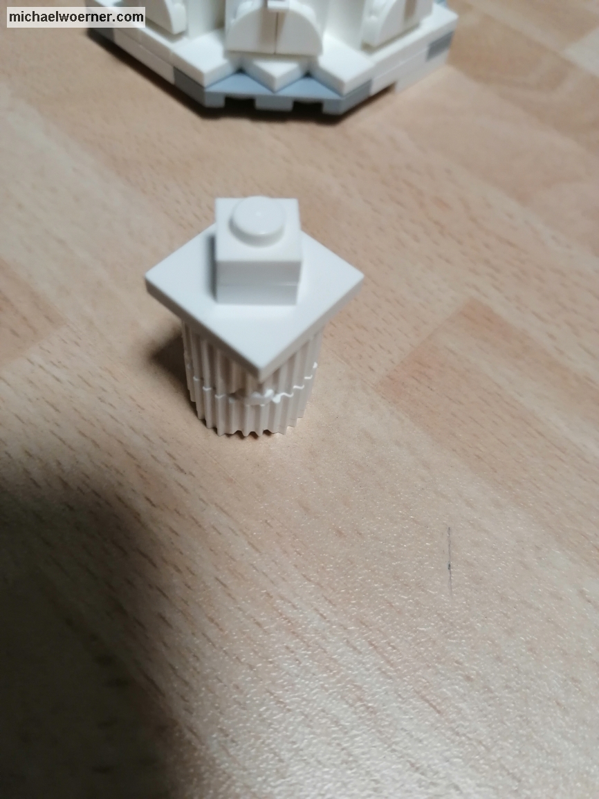
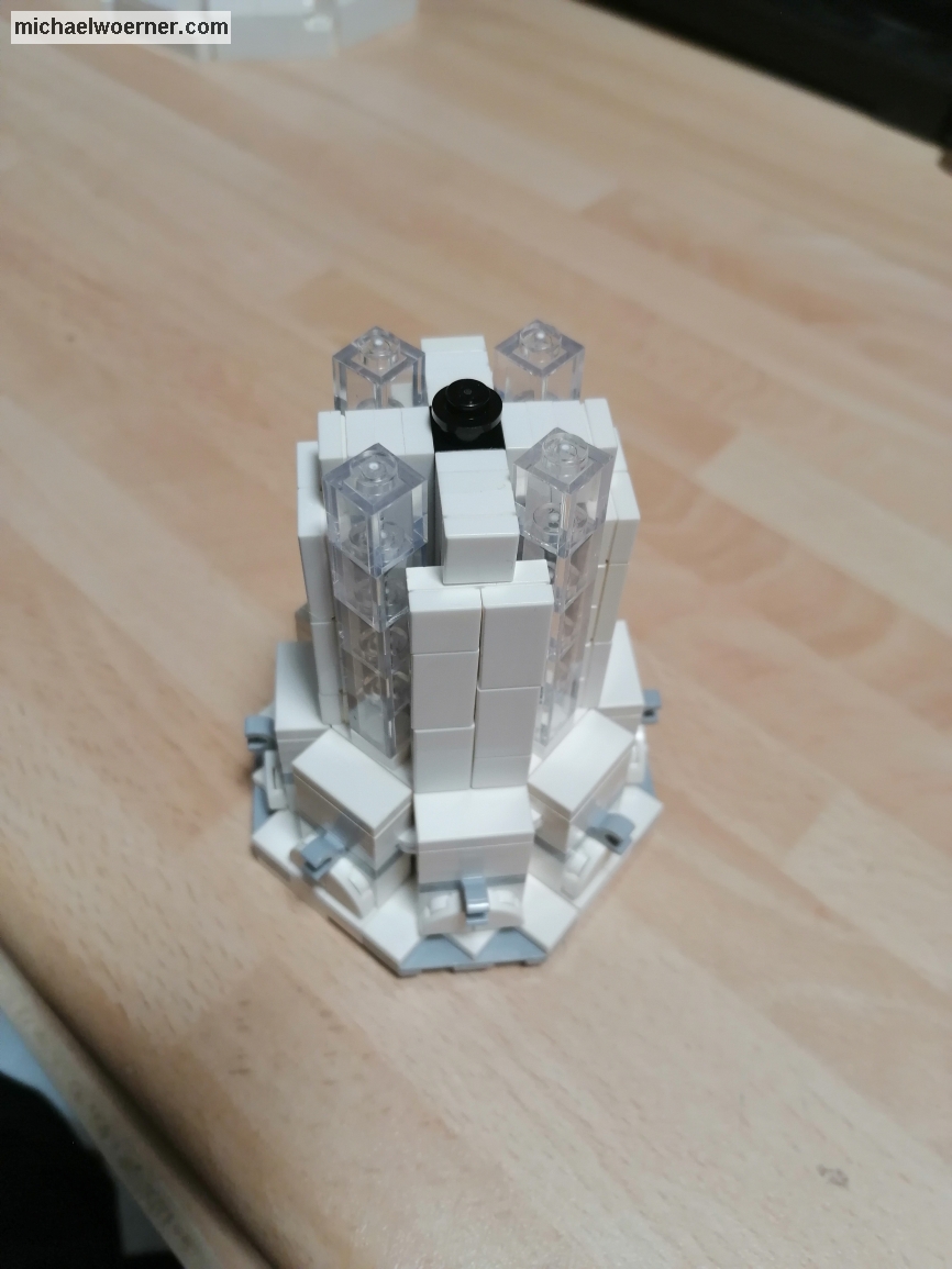
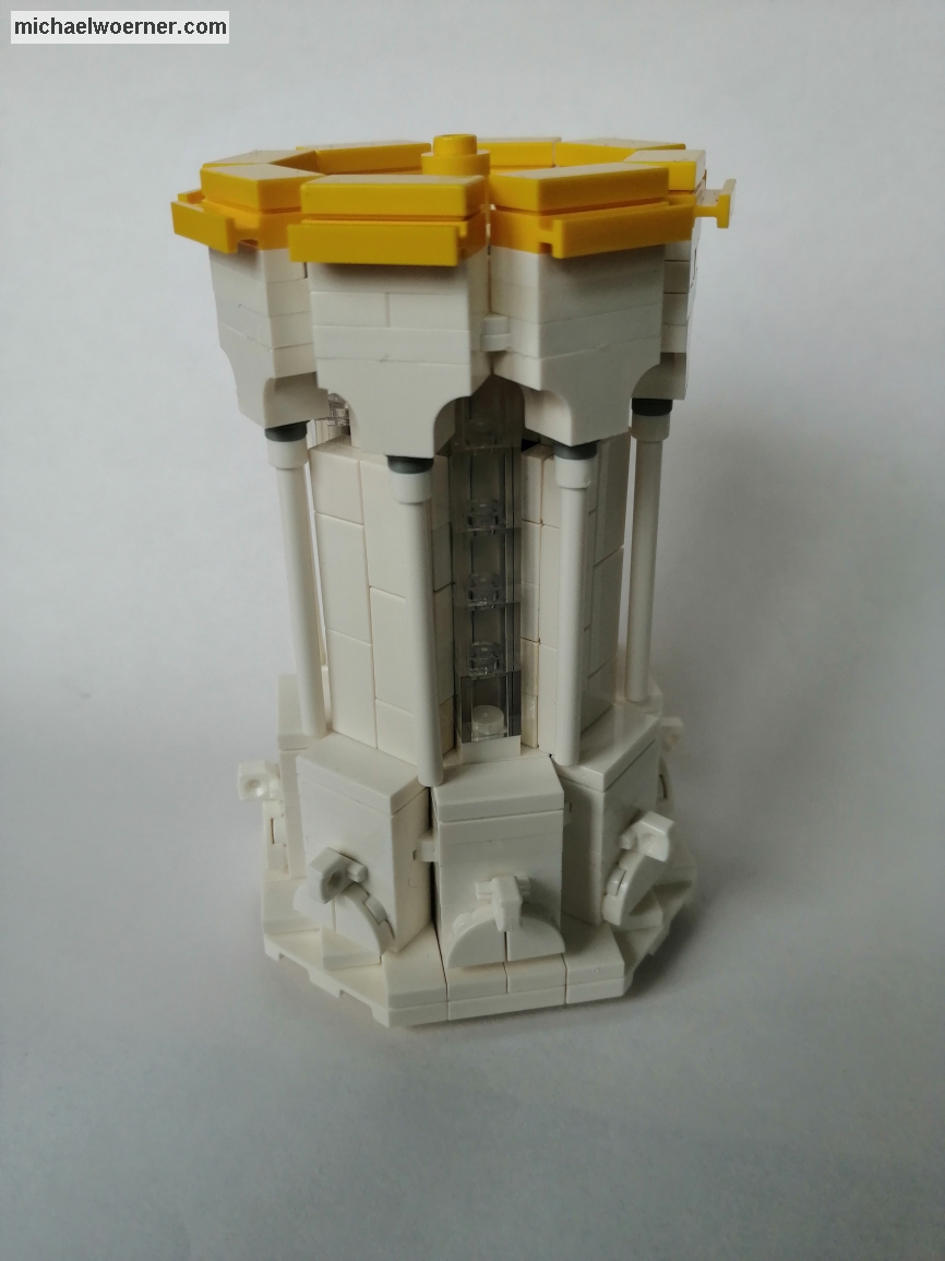
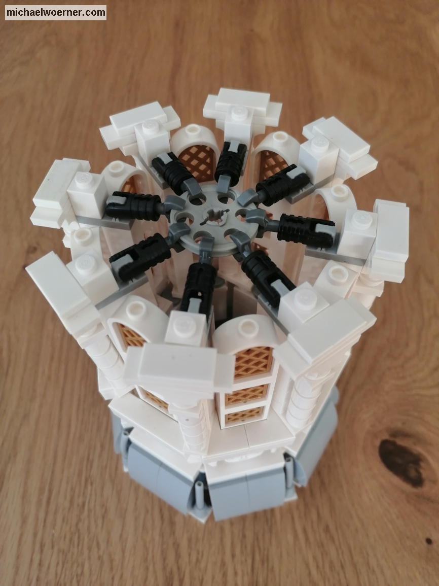
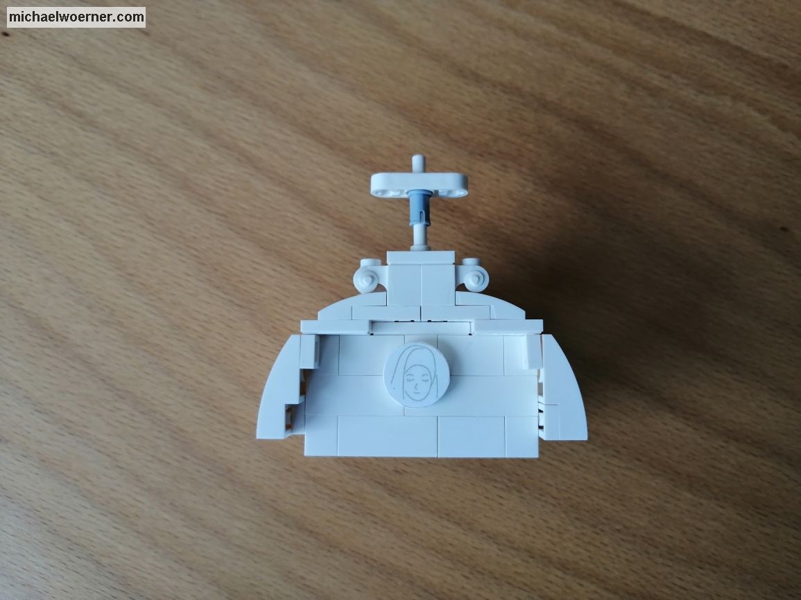
For the large dome with the 7 pins inside diameter the measure does not go unfortunately completely up to the top, therefore no 1×1 brick fits with the pins at the sides (4733) as conclusion. That’s why I have to attach the top differently than the small dome. I was looking for parts with the right dimension to make the resulting gap between wall and axle as small as possible to avoid slagging and thus also to center the tip. I had tried connectors (62462) and bushes (3713) but they are too small. That’s when a technic gear (4716) fell into my hand and it was a pretty good fit. To avoid falling out and to minimize the slagging even more, I put 2×2 round plates (4032) on the axle as a lower end and thus clamped the tip.


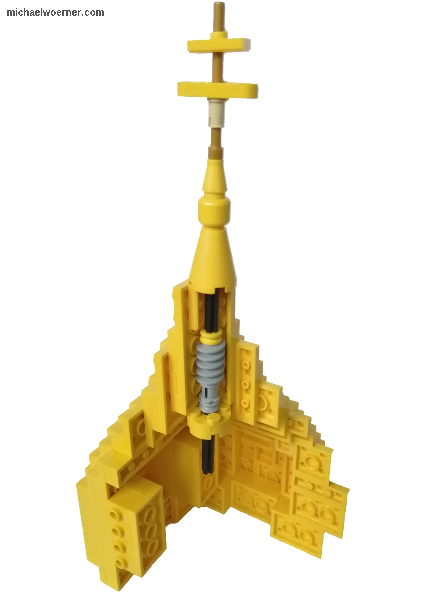
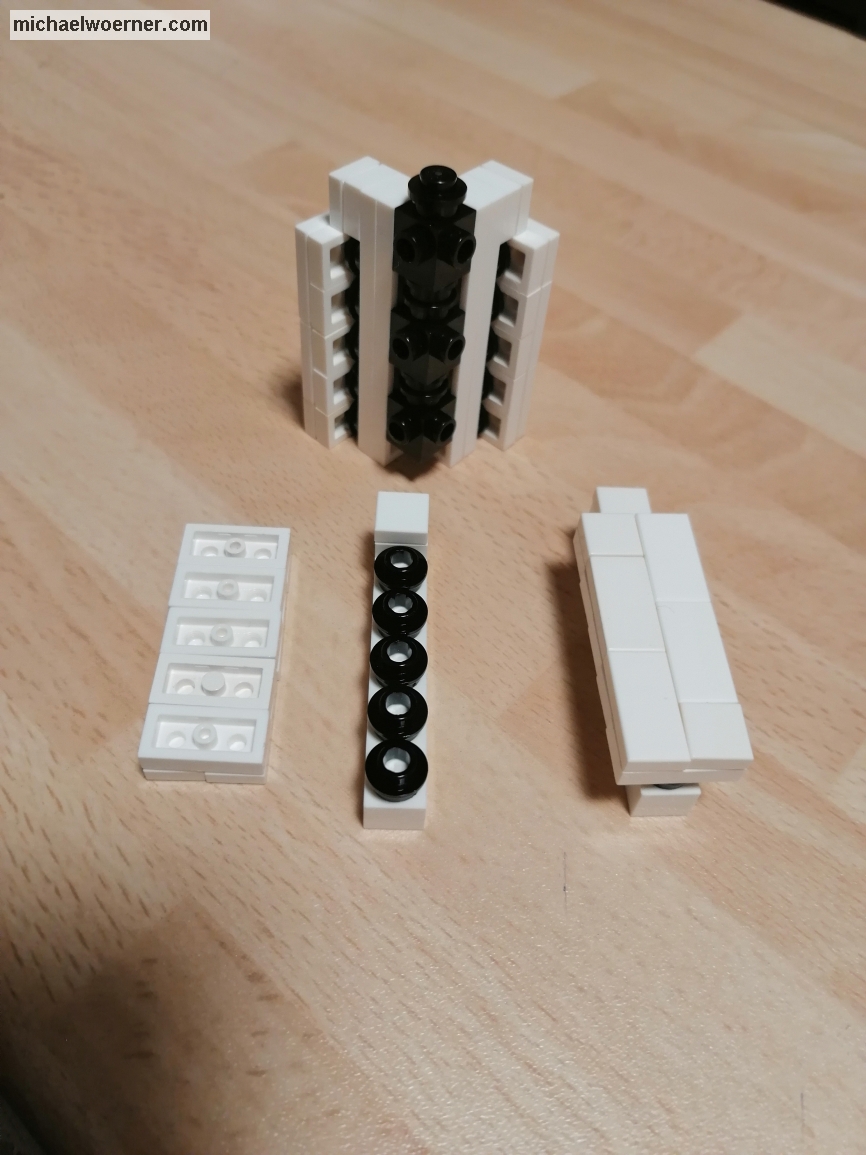
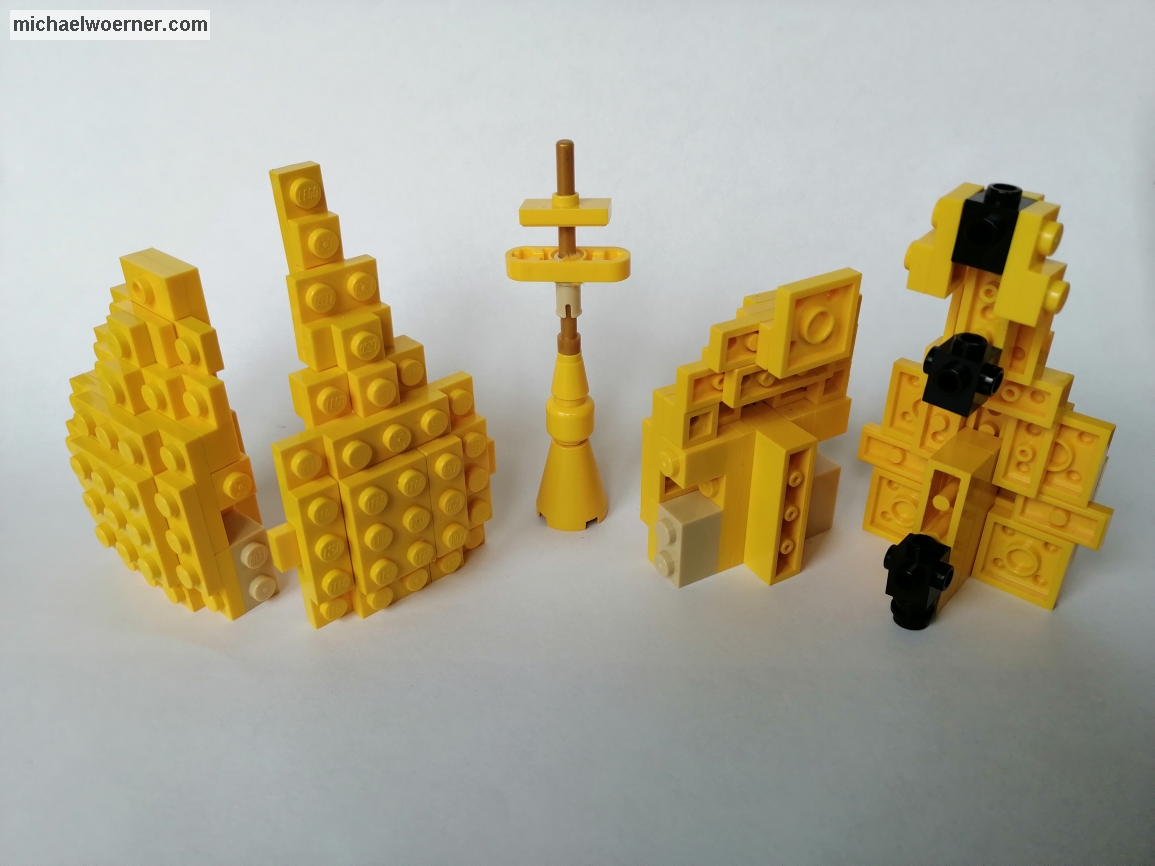
One thing bothers me. Unfortunately, I have not found a better solution. It is against the usual rules, but how else would I implement it? It’s about the Orthodox crosses. These have, in contrast to Christian ones, not one but 3 crossing arms, the upper one being smaller than the middle one and additionally an even smaller, oblique one at the very bottom. This is impossible to implement with Lego® means in my scale. I decided to leave out the slanted bottom one. The middle one is a thin 1×3 liftarm (6632). This one has a receptacle in the middle to put the bar through and fits pretty well in size.
The crossing arm above it should be smaller. There would be a plate 1×2 or similar in dimension best. Unfortunately, there is nothing that is yellow or gold colored that has these dimensions and a matching hole in the middle. After much thought and hassle, I drilled 1×2 Jumperplates in the middle and put them on the bar. This is my solution until I find something better or Lego launches a corresponding part.


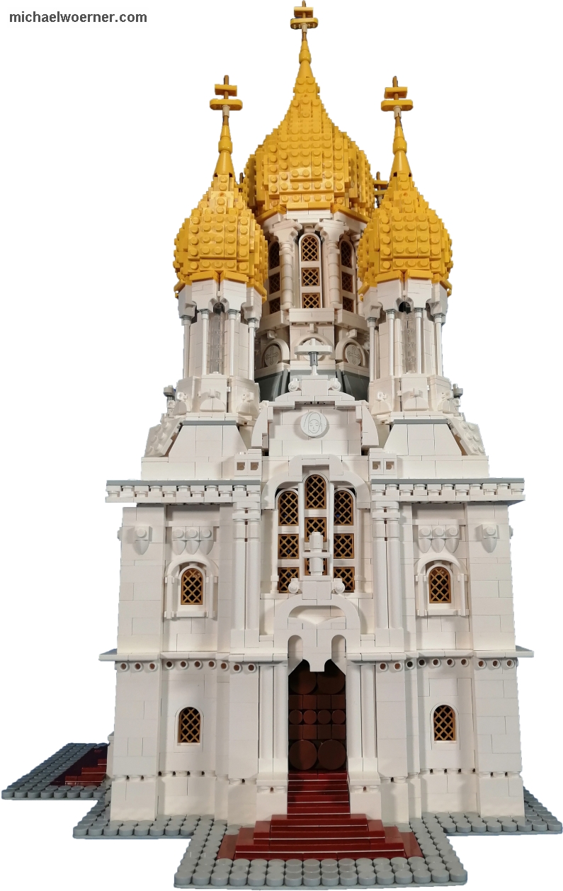
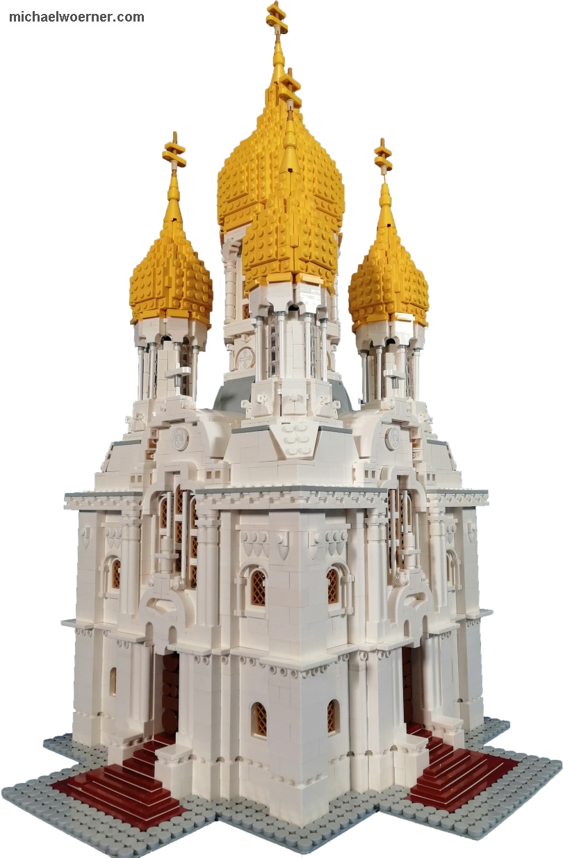
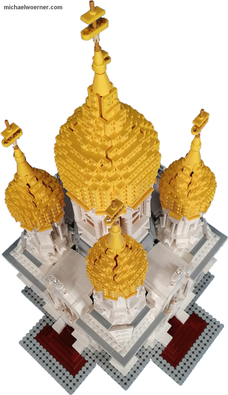
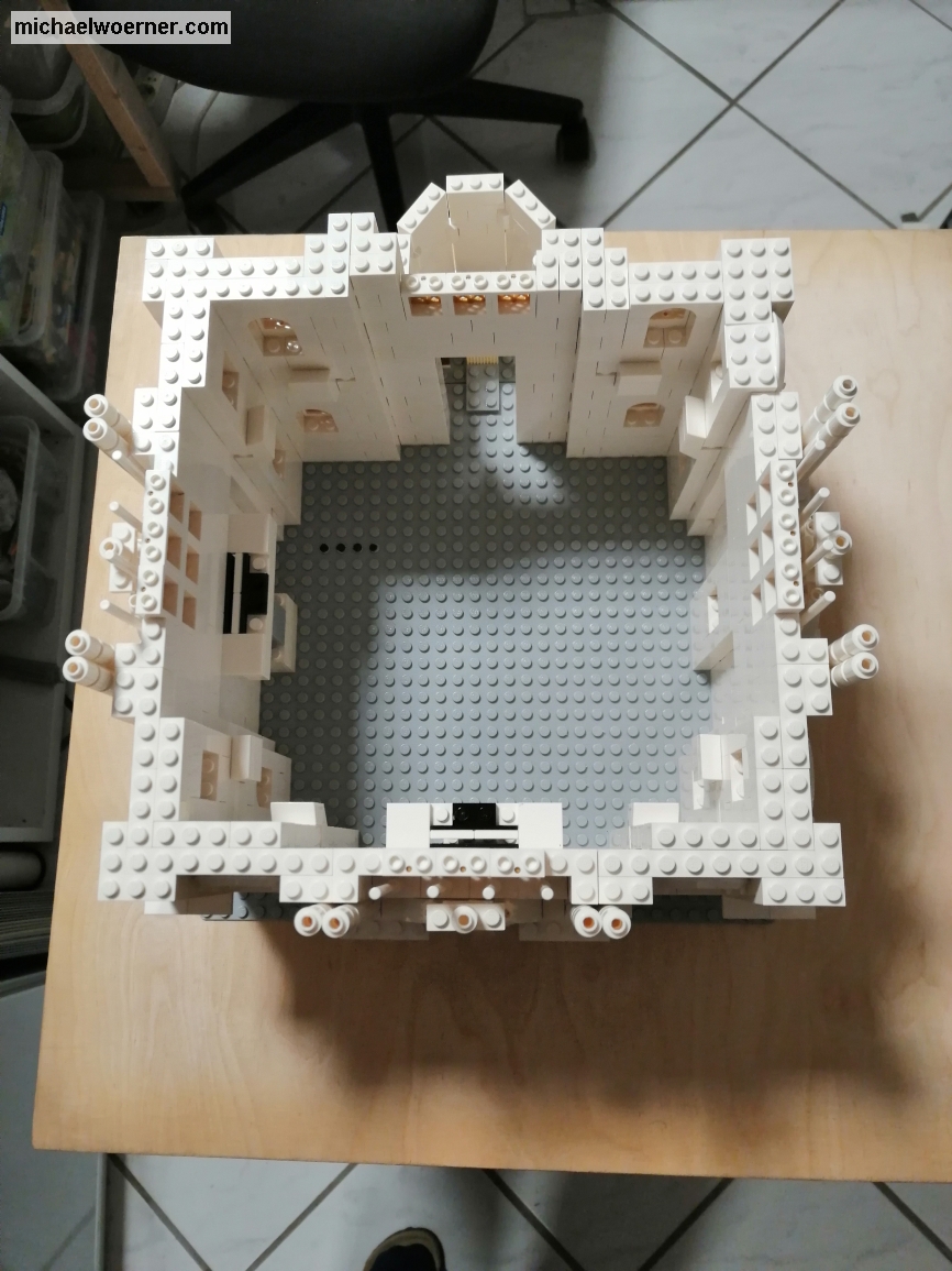
Now a few more numbers about the model. The construction time was about 90 hours spread over 4 weeks and I installed about 5500 parts. The scale is about 1:70.

Now there’s only one thing left. I hope you enjoyed the show. Feel free to leave a comment. I also welcome criticism and suggestions.

Maybe I’ll see you at an exhibition
Michael

A new model is made – part 6

The central tower is built and now comes the construction of the 4 corners on the model. Today I reveal to you that 4 more towers are being built to fill in the corners.

=== ATTENTION, I used a lot of pictures in this post! ===

They are relatively small diameter towers with 8 columns and 4 windows. I tinkered a lot and discarded it because it didn’t fit, wasn’t pretty, or just wasn’t sturdy enough. I would like to share my development steps with you and hope that the coming pictures with a little explanation will be sufficient to clarify the difficulties that arise with such a model. Maybe I’ll show you some ideas how to realize such shapes that you haven’t thought of before.


In the pictures you can see, the building corners have 8×8 pins and form an octagon. This is the base on which every tower is built. The inner “stools” are intended to give the windows built above them more stability so that they do not tilt inwards.


After that, the columns, windows and walls had to be accommodated in some way. As you can see from the previous picture, windows are not the problem. They are placed centered on the jumper. I had a solution that would have worked, but the walls were not high enough due to the plate + jumper + plate construction. To put the ring on it, I would have had to put another jumper on it. I also discarded this version.
But the columns and the walls should become a challenge, because the tower needs to continue above the windows. Finding a stable connection that is evenly round/octagon and fits on the lower part . . .
But see for yourself. Here are my (failed) attempts:


As seen above, the windows are placed at a 90° angle to each other. The walls are put on bricks with 4 pins on the sides (4733) and then stuck between the windows.


The pillars are in a ring in front of the walls and windows and run out in an arch to each other. They are connected to each other by hinged plates. The spacing of the sides cannot be connected to the normal Lego® grid. I had started to attach a hose ring to the inner part and then connect the outer part to it. But this proved to be unstable and difficult to implement.


Therefore, I have used the hoses elsewhere. The modified bricks with 4 pins have them perforated and a hose fits right in there. On the ring side there are round 1×1 plates with the same hole, which I used to fix the walls. The hole is provided with the same diameter.


Until next time

A new model is made – part 5

Today is the day. I think in the end it will become clear what kind of building is being constructed. As always, I’m interested in your solutions. Post them in the comments.

I start building the central tower today. I had finished the substructure in the last part and now I start thinking about how to divide the 8 windows, columns and walls in between. I am already sure that I will use the hinge plates (2429c01).

But before the windows and the rest I start with the foot of the tower. This tapers in an arc towards the top. This means that even less space is left for the windows & Co. I start by building 2x2x3 slopes (3768b) on top of the hinge plates, 8 pairs make the base. The size is just right and fits exactly in the gap between the barrel roofs. This leaves me with 4 pins on the outside and gives me the ledge. Later I exchange the 2x2x3 slanting bricks with curved slope 2×4 (93606). It’s more like the real tower. Between the resulting vertical 45° gaps I put a 1×1 cone with a hose.

I connected each element of the octagon with a 2×2 plate (3022) and a 2×2 wedge plate (26601). It’s such an exact fit in the angle that the hinges won’t move! Is also logical, because the wedge plate is provided with 45° angle. 8×45°=360°, as planned 😉


Directly above it follows a pedestal with an arch with a relief in it. I’m going to do this again with mudguards. But this time I use the others with the higher rounding (50745). They’re coming in a row behind the sill. But there is not enough room for 4 pins anymore. I build the socket alternately 2 and 4 pins wide at the front, behind all 2 pins wide. With the window sill above, I get a row further ahead, because the sill is slightly out and I’m back in the grid for the hinge plates to attach.


Then come the windows with the walls between them and the column in front. In the picture you can see how I did it. A description would probably not be understandable. I attach the top ring above the windows and the columns with a 1×2 jumper plate on the window and a 2×3 plate.


That completes the tower. The report about the dome and how it goes on with the roof is next time.

Until next time

A new model is made – part 4

Now that the second floor is almost finished, I have to think about how to build the transition to the next area in this fourth part. There, barrel roofs are installed above the middle windows. The corners spring back a little and taper towards the top and centrally there is a tower.

I start with the barrel roofs and had thought about using the arches 1x6x3 1/3 (6060) to implement them. Unfortunately, the roofs would then be too wide with 12 pins. So I need another solution and had created a narrower roof using the SNOT technique (SNOT = Studs Not On Top) which fits just fine. For this I use curved slopes (24309 + 50950) for the sides and tiles on top, connected to the sides by bricks with pins on the side (87087). I rebuilt this roof shape later and also used the curved slopes at the top, because it came even closer to the real shape.


Since I haven’t built any columns in the building that can hold the tower, I need to come up with a design that is capable of holding this structure. It was clear that technic bricks must be used here. Only these are stable and narrow enough to bridge the distance between the outer walls. To build an intersection, in my case the best way is to use the square technic bricks. I use the 40344 because that’s what I have on hand. I figured with technic pins the elements would connect tightly enough to support the tower load. Later it turned out that the weight of the tower was so high that the structure underneath was sagging a bit. Therefore I built a column of two 2×4 bricks in cross bond underneath.

As mentioned above, the corners in the next level jump back a little and taper with the height a little. The vertical outside corner is also beveled and not an easy task to implement. The most suitable are bevelled plates. Unfortunately, this is not available as a tile. That would look best. I had the shape with 2 of these 2×3 wedge plates (43 222 + 43 723) and it fit well into the gap, but the fixing was not possible in normal way. I had no choice but to clamp. Not very stable, but enough for a stationary model.

The last step for today is the tower base, it was easy to build. With bricks Facet 4×4 (14413) the substructure was quickly completed.

With these pictures I end today’s report. I think by now you’ve guessed what this is going to be. Write me your solution in the comments.

Until next time.

A new model is made – part 3

Last time I built the first “foundation walls. ” Today I would like to report on the further construction of the wall with the corresponding openings, corners and niches.

After the initial considerations regarding the basic form were implemented in the first construction phase, care must now be taken to maintain the individual heights. The principle is the same as for the width of the building. I put the horizontal steps and heights of the windows, cornices and individual floors together in proportion to the width that already existed. Here it is important to take the same measurements, otherwise the height will not be correct later and the building will be too low or too high. In height the realization is a bit easier, because Plates have a height of 3.2mm and therefore only take up a third of his Brick.

I had already considered using ready-made window elements in the last part. The choice was 2 pins wide, 3 rows high, semi-circular windows (30044) with grilles (30046). Unfortunately, the color selection is very limited with Lego® and with grids in particular. I decided to go with the gold because the contrast with black compared to the white walls, would be way too stark. When installing, I had to decide whether to use jumperplates (15573) to move the windows back half a brick.It looks more and more pleasing, and if you look at reality, it is very often the case. Unfortunately, I would have caught a problem 3 rows further. The windows have an arch at the top and a pin in the middle. The standard arches framing the windows at the top would not fit because of this pins. Fortunately, the grilles are not mounted in the middle of the window, but on one side. Thus there is the possibility to set the grid inside, and thus offset back, or outside flush. I decided to go inside.

The next step are the columns. My building has obstructed columns. Unfortunately, in at least 3 different thicknesses. At my scale, a wider column than 1 pin is not feasible, or the part will be too wide and I won’t be able to keep my scale. That means compromise again. But we Lego model builders are used to that. I decide to use the 1x1x6 rods (43888).

The next hurdle is the transition to the next floor. There’s a ledge all around here. Of course only a few cm wide in reality. For my model this means only 1-2mm. This modified plate (32028) comes directly to my mind. But you can’t because there are no inside or outside corners. That wouldn’t look good. The same applies to the jumper plates. So slabs or tiles? With Plates I have the pins standing, I don’t like that. Tiles do not have these and so they are my choice. At the same time, they also allow to build the model Modular. To create a separation point for better transportation.


The second floor is almost identical to the first. But the windows have much more ornaments and a column frame all around. with the little space that the scale allows me to implement a tricky thing. I have re-entitled the side columns with 3 bars (87 994) and the upper arch with a mudguard (98282) and am satisfied with the result. The arches in the middle are next. I tried to recreate it with different elements, but it’s not that filigree with Lego. Nevertheless, you can see what it is meant to represent. The columns in front of the windows behind them are realized by rods (63 965) and cut tubes (75c24).

The picture still shows parts that need to be replaced. I either don’t have the part there or it’s in the wrong color. In order to move forward, I therefore use these and can continue building like this.

That’s it for today, until the next post.

a new model is made – part 2

Now is the time. As announced, the second Part of the construction of the model.

Let’s start with the ‘what’. I don’t want to give too much away yet. It’s not difficult either and you’ll figure out what it’s going to be pretty quickly. But this much in advance: it will be a building that really exists.
I chose a 32×32 pin baseplate as my measurement. In the run-up I made many photos of the object and informed myself about the real dimensions, searched in the internet resp. determined from photographs. One edge length has about 17 meters. The building has a square footprint, which makes it quite easy to get the model onto a 32 baseplate. Each Lego® brick has a width of 8mm per pin, so a 32 baseplate is 32 x 0,8cm = 25,6cm wide/long.

Watch out, here comes math!!!
Scale = 1 : scale number
Scale number = true size : model size

For me, this means that I have a scale of 1:70 at 17,5m side length. Thus 70cm in real complies 1cm model. You can work with that. Now I take a picture where the building is completely visible from the side and I separate it into the distinctive areas, bounded by corners, projections, windows and stairs. I measure the distances and put them in relation to my available width. It almost never fits precisely because of the 8mm grid. But a little adaptation and consideration (how wide is a finished window?) then give me the solution. I decided to use finished window elements and not build them myself out of parts. The scale allows this and reduces the complexity and the total number of parts and thus the price.

For ease of understanding, I have given numbers in brackets after the parts described. These are the design numbers of Lego.

I have a bird’s eye view picture with another from the side, and I’m using those to lay the first layers of bricks. The rounding on the back is a little tricky and it took me some tries to get it to work that way. The angles do not allow the bricks to be fixed to the base plate, the hinges give a lot of movement. To counteract this, I used angles (99207 + 32952) with tiles on the base plate to keep the distance to the wall as small as possible and the curve evenly in shape. I use 2 different hinges for the rounding. One as a stone (3830c01), the other as a plate (2429c01). A comparison with the picture from the side shows me that this could fit. I’ll keep building, if it doesn’t fit later I can change it. I love plug-in systems 😉

That’s it for today. Until the next part, then with more pictures

a new model is made

In the next few days, I will publish a kind of diary here at this point. It’s about how a new model of me comes into being and what problems I’ve encountered in the process. Using pictures and descriptions, I show what I tried and how I finally built. With this diary I accompany the construction of the model from the first step to the completion. You have a chance to guess what it should be. The dissolution, if you don’t know it already, comes to an end.

Have fun